
The complete steel detailing package.
Model, drawings and machine files — structural steel and full miscellaneous / ornamental metals scope, delivered by a US-based team, coordinated to AISC standards, and senior-checked before it reaches you. Choose a capability below.
Structural Steel Detailing
Structural steel detailing is where a project's design becomes buildable. We translate the Structural Engineer of Record's design — the S-sheets — into precise, fabrication-ready shop drawings, erection drawings and a coordinated 3D model for the primary frame: beams, columns, braces, trusses and their connections.
We detail in Tekla Structures at LOD 350/400, so every member, plate, bolt and weld is modeled once and drives every drawing, report and CNC file automatically.
- Assembly & single-part drawings — each with a unique piece mark
- Erection & framing plans by floor and elevation, with sections
- Anchor rod setting plans issued early for the foundation contractor
- Advance Bills of Material to absorb 6–12 week mill lead times

Miscellaneous & Ornamental Metals Detailing
Miscellaneous and ornamental metals are where detailing skill really shows — and where many shops fall short. Woodell gives misc metals equal billing with structural steel.
We detail stairs (egress, monumental, spiral, mono-stringer), handrails and guardrails, ladders with safety cages, platforms and catwalks, gratings and checkered plate, embeds and weld plates, canopies and architecturally exposed structural steel (AESS). This work demands strict OSHA/IBC egress geometry and, on exposed members, the tighter tolerances and finish discipline of AESS.
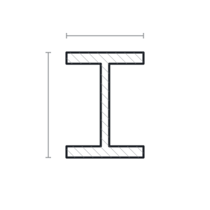
Steel Shop Drawings
Shop drawings are the documents your shop floor actually builds from. We produce fabrication-ready assembly (main-member) and single-part drawings that carry exact dimensions, cuts, copes, holes, bevels, welds and surface prep — each element tagged with a unique piece mark.
Because drawings and machine files export from the same model, part lengths, hole positions, bevels and copes translate directly into machine coordinates — reducing shop-floor interpretation and rework.
- AWS weld symbols and complete weld maps
- Bolt schedules and shop bill of material per drawing
- DSTV/NC1 for drill lines, saws and coping; DXF for plate profiling
- Fabricator formats — FabTrol KISS, CSV/XML, nesting-ready lists
Erection Drawings
Erection drawings tell the field crew exactly what goes where. We prepare clear field-installation drawings for erectors and GCs showing the location, orientation and attachment of every shipping piece, so crews assemble the structure safely, accurately and on schedule.
Piece marks and connection details are coordinated across shop and erection drawings so the marks on the steel match the marks on the plan. Field bolt lists distinguish snug-tight, pretensioned and slip-critical joints per RCSC.
- Erection / framing plans by floor and elevation, with sections
- Anchor rod setting plans
- Field bolt point-to-point lists and summaries
- Erection sequence drawings for safe, orderly assembly
3D BIM Modeling & Coordination
Every Woodell package begins as an intelligent 3D BIM model. Built in Tekla Structures (with SDS/2 and Advance Steel available) at LOD 350 for coordination or LOD 400 for fabrication, the model contains every member, plate, bolt, weld and connection — and becomes the single source of truth for all drawings, reports and CNC files.
We coordinate the steel model against architectural, MEP and concrete models via IFC and Navisworks, resolving steel-to-steel and steel-to-MEP clashes in design rather than during erection. Open-BIM interoperability (IFC2x3/IFC4, CIS/2) and in-model review through Trimble Connect keep every trade working from the same geometry.
Connection Detailing & Coordination
Connections are where a steel frame succeeds or fails. We model and detail bolted and welded connections — shear tabs, double-angle and seated clips, end-plate and extended end-plate moment connections, brace gussets, base plates, column and beam splices — and coordinate closely with your engineer of record and delegated connection designer.
We stay firmly in the detailer's lane: connection design is performed by a licensed PE (yours or the fabricator's delegated designer) per AISC 360 Chapter J. We model the resulting geometry accurately, verify it against the stamped calculations, flag conflicts through the RFI process, and detail it for the shop. For seismic frames we detail per AISC 341 and AISC 358 prequalified types.
- Checked connection geometry integrated into shop drawings
- Delegated connection design coordinated into the model
- Seismic details per AISC 341 / 358 (RBS, BFP, end plate)
We match the platform to your shop.
Tekla Structures is our platform of record — validated by a 2016 Tekla North America BIM Awards category win — and we work in SDS/2, Advance Steel and AutoCAD as your workflow requires.
Tekla Structures
3D BIM to LOD 400. Exports IFC, CIS/2, DWG, DSTV/NC1 and DXF. Model sharing and in-model review via Trimble Connect.
SDS/2 · Advance Steel · AutoCAD
Code-based intelligent connection detailing, AutoCAD-based modeling with Revit/Navisworks integration, and 2D drafting for legacy detail production.
Navisworks · Trimble Connect · Tekla Model Sharing · point-cloud scan-to-BIM
IFC2x3 / IFC4 · CIS/2 · DWG · DXF
DSTV/NC1 · DXF · FabTrol KISS · CSV / XML
Multi-platform capability (SDS/2, Advance Steel, AutoCAD) is provided by the firm; Tekla Structures use is publicly verified via the Tekla BIM Awards (2016 Small Projects category winner).
Send your contract documents. We'll scope it.
We'll recommend the right combination of services for your project — structural, misc metals, or both.